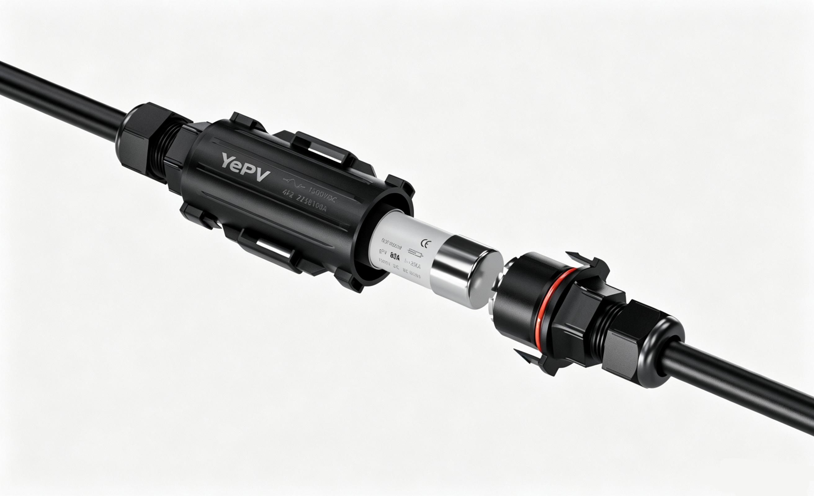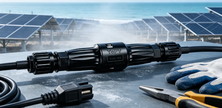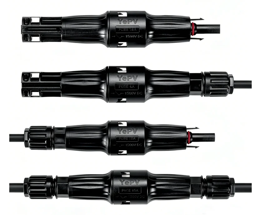
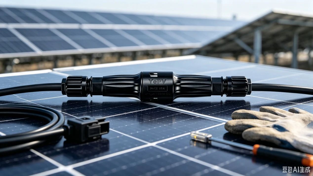
As the PV industry moves to higher voltages, 1500VDC has become standard for large ground-mount and commercial projects. Higher voltage lowers system cost and raises efficiency, but it also tightens the safety requirements on DC connectors and overcurrent protection.
Why 1500V demands extra care
MC4 is the accepted industry interface, and the newer MC4-EVO2 family supports 1500VDC. But 1500V brings higher insulation requirements, harder arc extinction and stricter installation standards. Under NEC 2023, DC systems from 1000V to 1500V running outside a building require conductors rated at least 2000V and must follow the wiring rules of 690.31(G).
Loose or mismatched connectors are a leading cause of PV fires, and most incidents trace back to poor crimping or damaged conductors. The higher the voltage, the smaller the margin for error.
Before you start
Confirm 1500V compatibility
Not every MC4 connector is rated for 1500V. Confirm TÜV or UL certification and look for IEC 62852 or UL 6703 marking — the two key standards for 1500VDC PV connectors.
Prepare the right tools
Never crimp MC4 terminals with a generic multi-purpose tool — a quality dedicated crimper is what makes the crimp repeatable and UL-compliant.
Choose the fuse rating
1500V inline fuse connectors typically cover 2A to 32A or higher. Calculate 1.56 x Isc, keep the result below the module maximum series fuse rating, and confirm the fuse voltage rating exceeds the temperature-corrected string Voc.
Step-by-step installation
Step 1 — De-energise
Confirm the DC switch is OFF. If the system is live, bring string current below 0.5A before opening the switch. Never work on a live 1500VDC circuit.
Step 2 — Strip correctly
Strip roughly 6mm of insulation. Too short and the conductor will not seat; too long and copper is exposed. MC4 inline fuse connectors normally accept 2.5mm², 4mm² or 6mm² PV cable.
Step 3 — Crimp the terminal
Crimp with the dedicated MC4 tool to form a cold-weld between strands and terminal. Then verify: a pull test must not move the terminal, contact resistance should be below 0.35mΩ, and per IEC 62852 the post-installation increase must stay under 5mΩ.
Step 4 — Assemble the housing
Push the crimped terminal into the male or female housing until it clicks, then tighten the gland — around 1.0 to 1.2Nm. Over-tightening can crack the gland through thermal cycling.
Step 5 — Mate the connectors
Push male and female together until a clear click confirms the latch. Incomplete mating causes arcing or overheating and damage from poor assembly is generally outside warranty.
Step 6 — Manage cable stress
Tension on the cable can pull a pin back slightly and create a spark gap. Leave a service loop near every connector pair and tie incoming and outgoing cables together, or secure both to a common member. Y-connectors and branch connectors must be supported by a tray or rail rated for at least 10kg so no stress reaches the inverter terminals.
Step 7 — Seal unused ports
Every unused DC terminal on the inverter or combiner box must be closed with an MC4 waterproof cap to preserve IP68 protection.
Safety considerations
Five common mistakes
Post-installation checklist
When in doubt, follow the manufacturer instructions and the relevant standards: NEC Article 690, IEC 62852 and IEC 60269-6. Most PV fires start at a bad connection — the time spent doing it right once is always worth it.